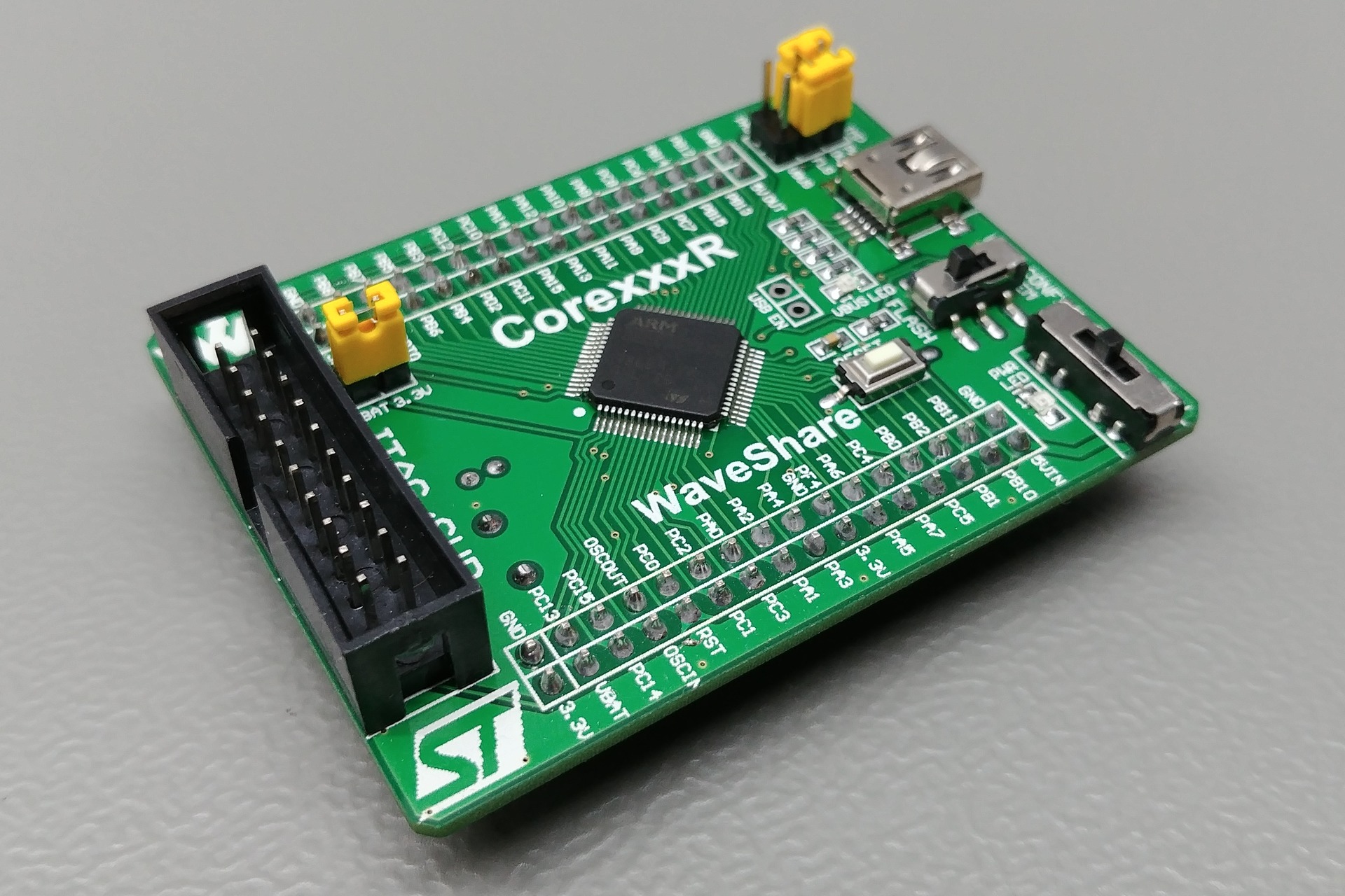
WaveShare Core205R board
STM32F205RBT6
Board
| Name | WaveShare Core205R board |
| Part | CorexxxR |
| Brand | WaveShare |
| Origin | China |
Microcontroller
| Part | STM32F205RBT6 |
| Manufacturer | ST-Microelectronics |
| Core | Arm Cortex-M3 |
| Max. Clock Speed | 120MHz |
| Package | LQFP 64 pins |
Internal memories
| FLASH | 128KiB |
| SRAM | 64KiB |
Oscillators
| HSI | 16MHz |
| LSI | 32kHz |
| HSE | 25MHz |
| LSE | 32.768kHz |
Power
| Sources | Any +3.3V pin (+3.3V) 5Vin pin (+5V) USB connector (+5V) |
| VDDA pin | No |
| VSSA pin | No |
| VREF- pin | No |
| VREF+ pin | No |
| Backup battery | Pin |
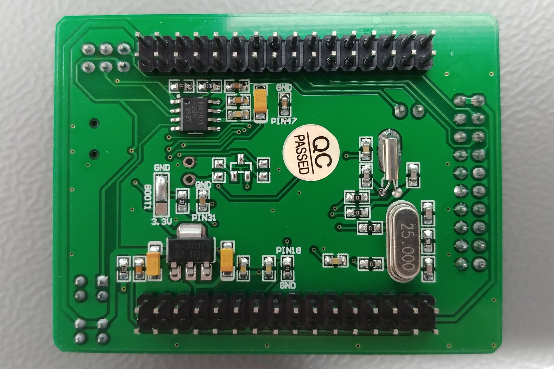
Regulator
| Manufacturer | Advanced Monolithic Systems Inc. |
| Part | AMS1117 (AMS1117) |
| Package | SOT223 3 pins |
| Input | +4.6V to +15V |
| Output | +3.3V @ 1A |
| Datasheet | AMS1117.pdf |
PCB
| Color | Green |
| Size (w x l) | 48mm x 64mm |
| Mounting | None |
Remarks
- Warning: The +5V pins on this board are directly connected to the +5V pin of the USB connector. There is no protection in place. Do not power this board through USB and an external power supply at the same time.
- Note: This is a generic board. There are other variations available with a different microcontroller, like on with an STM32F405RGT6 device.
Pictures
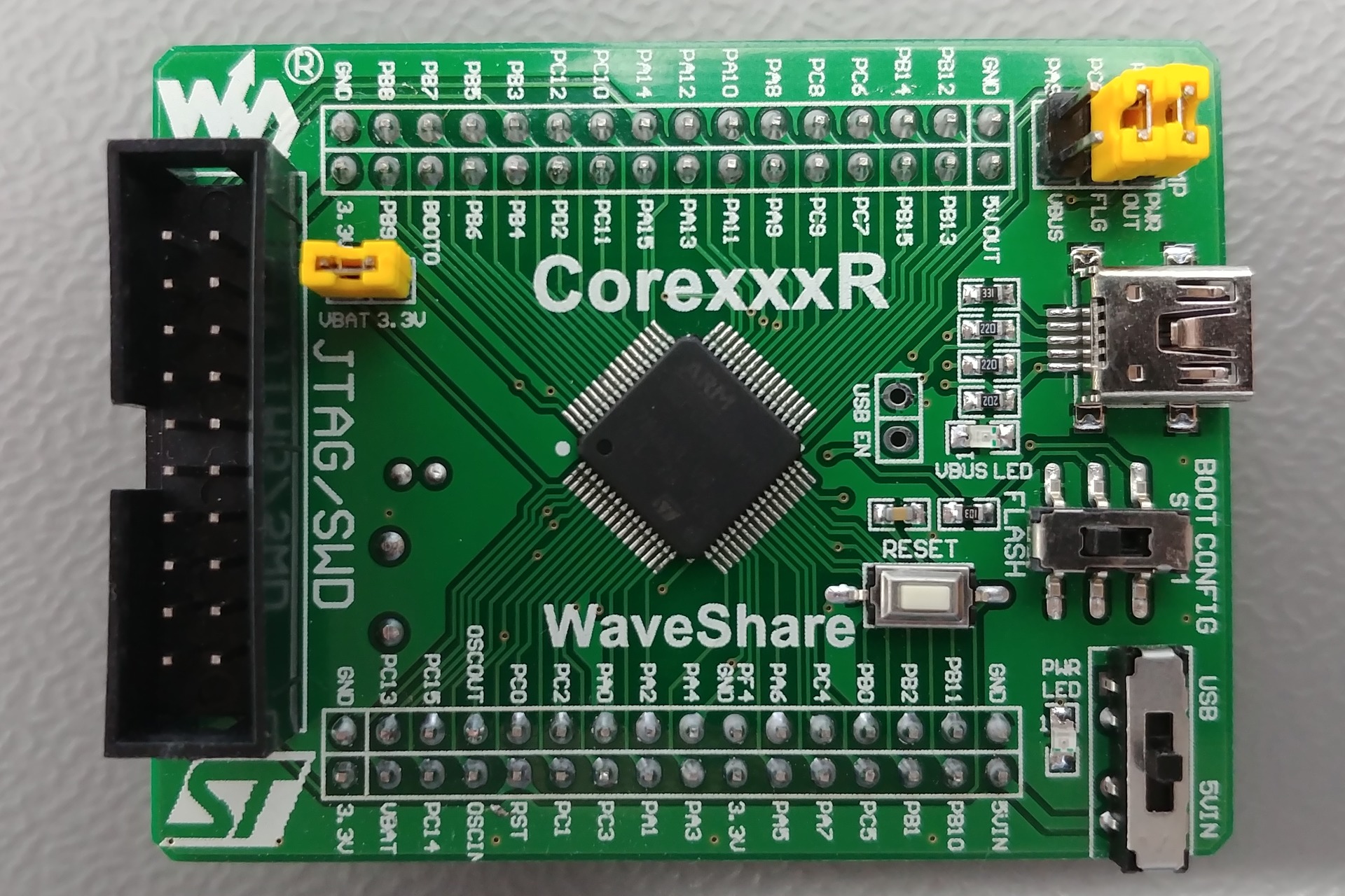
Connectors
Devices
Inputs & outputs
Reset button
| Name | RESET |
| Reference | - |
| Type | Button |
| Connected to | NRST |
| Mode | Active low |
BOOT0 switch
| Name | BOOT CONFIG |
| Reference | - |
| Type | Switch |
| Connected to | BOOT0 |
| Mode | N.A. |
+5V source selection switch
| Name | - |
| Reference | - |
| Type | Switch |
| Connected to | +5V rail |
| Mode | N.A. |
- Info: Selects the +5V power source. Can be set to USB, 5Vin pin, or none.
Vbat jumper
| Name | - |
| Reference | - |
| Type | 1-way jumper |
| Connected to | VBAT to +3.3V rail |
| Mode | N.A. |
USB OTG FLG jumper
| Name | OTG JMP |
| Reference | - |
| Type | 1-way jumper |
| Connected to | PC2 |
| Mode | N.A. |
USB OTG PWR OUT jumper
| Name | OTG JMP |
| Reference | - |
| Type | 1-way jumper |
| Connected to | PC1 |
| Mode | N.A. |
USB OTG VBUS jumper
| Name | OTG JMP |
| Reference | - |
| Type | 1-way jumper |
| Connected to | PA9 |
| Mode | N.A. |
Power LED
| Name | PWR LED |
| Reference | - |
| Type | LED |
| Connected to | +3.3V rail |
| Mode | N.A. |
VBUS LED
| Name | VBUS LED |
| Reference | - |
| Type | LED |
| Connected to | +5V rail |
| Mode | N.A. |
Connectors & headers
Header 1 properties
| Name | Unknown |
| Reference | None |
| Type | Pin header (2mm, 16x2, male) |
Header 1 pins
| # | Name | Function | Connected to |
|---|---|---|---|
| 1 | 3.3V | - | +3.3V rail |
| 2 | GND | - | Ground plane |
| 3 | VBAT | - | VBAT |
| 4 | PC13 | - | PC13 |
| 5 | PC14 | - | PC14 |
| 6 | PC15 | - | PC15 |
| 7 | OSCIN | - | PD0 |
| 8 | OSCOUT | - | PD1 |
| 9 | RST | - | NRST |
| 10 | PC0 | - | PC0 |
| 11 | PC1 | - | PC1 |
| 12 | PC2 | - | PC2 |
| 13 | PC3 | - | PC3 |
| 14 | PA0 | - | PA0 |
| 15 | PA1 | - | PA1 |
| 16 | PA2 | - | PA2 |
| 17 | PA3 | - | PA3 |
| 18 | PA4 | - | PA4 |
| 19 | 3.3V | - | +3.3V rail |
| 20 | GND | - | Ground plane |
| 21 | PA5 | - | PA5 |
| 22 | PA6 | - | PA6 |
| 23 | PA7 | - | PA7 |
| 24 | PC4 | - | PC4 |
| 25 | PC5 | - | PC5 |
| 26 | PB0 | - | PB0 |
| 27 | PB1 | - | PB1 |
| 28 | PB2 | - | PB2 |
| 29 | PB10 | - | PB10 |
| 30 | PB11 | - | PB11 |
| 31 | 5VIN | - | Vin |
| 32 | GND | - | Ground plane |
Header 2 properties
| Name | Unknown |
| Reference | None |
| Type | Pin header (2mm, 16x2, male) |
Header 2 pins
| # | Name | Function | Connected to |
|---|---|---|---|
| 1 | GND | - | Ground plane |
| 2 | 5V OUT | - | +5V rail |
| 3 | PB12 | - | PB12 |
| 4 | PB13 | - | PB13 |
| 5 | PB14 | - | PB14 |
| 6 | PB15 | - | PB15 |
| 7 | PC6 | - | PC6 |
| 8 | PC7 | - | PC7 |
| 9 | PC8 | - | PC8 |
| 10 | PC9 | - | PC9 |
| 11 | PA8 | - | PA8 |
| 12 | PA9 | - | PA9 |
| 13 | PA10 | - | PA10 |
| 14 | PA11 | - | PA11 |
| 15 | PA12 | - | PA12 |
| 16 | PA13 | - | PA13 |
| 17 | PA14 | - | PA14 |
| 18 | PA15 | - | PA15 |
| 19 | PC10 | - | PC10 |
| 20 | PC11 | - | PC11 |
| 21 | PC12 | - | PC12 |
| 22 | PD2 | - | PD2 |
| 23 | PB3 | - | PB3 |
| 24 | PB4 | - | PB4 |
| 25 | PB5 | - | PB5 |
| 26 | PB6 | - | PB6 |
| 27 | PB7 | - | PB7 |
| 28 | BOOT0 | - | BOOT0 |
| 29 | PB8 | - | PB8 |
| 30 | PB9 | - | PB9 |
| 31 | GND | - | Ground plane |
| 32 | 3.3V | - | +3.3V rail |
USB connector properties
| Name | Unknown |
| Reference | None |
| Type | USB Micro |
USB connector pins
| # | Name | Function | Connected to |
|---|---|---|---|
| 1 | - | VCC | +5V source selection switch |
| 2 | - | D- | PA11 via 22Ω resistor |
| 3 | - | D+ | PA12 via 22Ω resistor |
| 4 | - | ID | PA10 via 330Ω resistor |
| 5 | - | GND | Ground plane |
JTAG header properties
| Name | Unknown |
| Reference | None |
| Type | IDC (2.54mm, 10x2, male) |
JTAG header pins
| # | Name | Function | Connected to |
|---|---|---|---|
| 1 | - | VCC | +3.3V rail |
| 2 | - | VCC | +3.3V rail |
| 3 | - | TRST | PB4 |
| 4 | - | GND | Ground plane |
| 5 | - | TDI | PA15 |
| 6 | - | GND | Ground plane |
| 7 | - | TMS / SWDIO | PA13 |
| 8 | - | GND | Ground plane |
| 9 | - | TCLK / SWCLK | PA14 |
| 10 | - | GND | Ground plane |
| 11 | - | RTCK | N.C. |
| 12 | - | GND | Ground plane |
| 13 | - | TDO / SWO | PB3 |
| 14 | - | GND | Ground plane |
| 15 | - | RESET | NRST |
| 16 | - | GND | Ground plane |
| 17 | - | N.C. | N.C. |
| 18 | - | GND | Ground plane |
| 19 | - | N.C. | N.C. |
| 20 | - | GND | Ground plane |
Devices
MIC2075 properties
| Name | Unknown |
| Reference | Unknown |
| Manufacturer | Microchip Technology Inc. |
| Part | MIC2075 |
| Marking | 2075-28M |
| Datasheet | MIC2075.pdf |
| Package | SOIC 8 pins |
| Description | USB High-Side 500mA Current Limiting Power Switch |
MIC2075 pins
| # | Name | Function | Connected to |
|---|---|---|---|
| 1 | - | EN | PWR OUT jumper, pulled up by 10kΩ resistor |
| 2 | - | FLG | FLG jumper, pulled up by 10kΩ resistor |
| 3 | - | GND | Ground plane |
| 4 | - | NC | N.C. |
| 5 | - | NC | N.C. |
| 6 | - | OUT | USB 5V pin |
| 7 | - | IN | +5V rail |
| 8 | - | OUT | USB 5V pin |