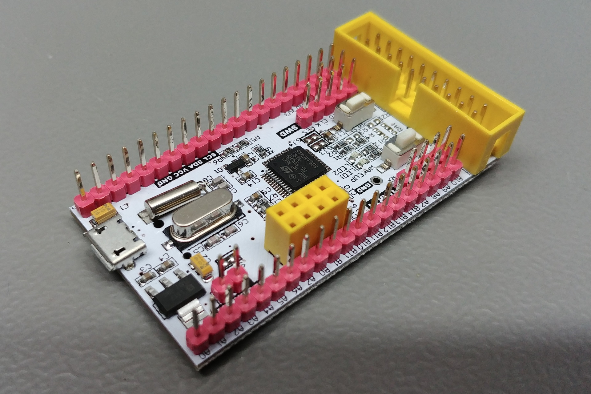
STM32xxxC8T6 Board
STM32F303CBT6
Board
| Name | STM32xxxC8T6 Board |
| Part | STM32xxxC8T6 DESIGN BY WAIMAN |
| Brand | Unknown |
| Origin | China |
Microcontroller
| Part | STM32F303CBT6 |
| Manufacturer | ST-Microelectronics |
| Core | Arm Cortex-M4 |
| Max. Clock Speed | 72MHz |
| Package | LQFP 48 pins |
Internal memories
| FLASH | 128KiB |
| SRAM | 32KiB |
| CCM | 8KiB |
Oscillators
| HSI | 8MHz |
| LSI | 40kHz |
| HSE | 8MHz |
| LSE | 32.768kHz |
Power
| Sources | Any +3.3V pin (+3.3V) Any +5V pin (+5V) USB connector (+5V) |
| VDDA pin | No |
| VSSA pin | No |
| VREF- pin | No |
| VREF+ pin | No |
| Backup battery | Holder (12.5mm / 12) |
Regulator
| Manufacturer | Unknown |
| Part | Unknown (1117) |
| Package | SOT223 3 pins |
| Input | +4.6V to +12V |
| Output | +3.3V @ 500mA |
| Datasheet | Unavailable |
PCB
| Color | White |
| Size (w x l) | 32mm x 60mm |
| Mounting | None |
Remarks
- Warning: The +5V pins on this board are directly connected to the +5V pin of the USB connector. There is no protection in place. Do not power this board through USB and an external power supply at the same time.
- Note: This board has solder bridges SJ3 and SJ4. These connect pin 35 and 36 respectively and provide power on devices that have power pins there. On boards with devices that have PF6 and PF7 exposed on these pins, these bridges are cut.
Pictures
Resources
Devices
None
Inputs & outputs
Reset button
| Name | RESET |
| Reference | - |
| Type | Button |
| Connected to | NRST |
| Mode | Active low |
User button
| Name | WAKEUP |
| Reference | - |
| Type | Button |
| Connected to | PA0 |
| Mode | Active high |
Current measure solder bridge
| Name | - |
| Reference | SJ1 |
| Type | Solder bridge |
| Connected to | +3.3V rail to microcontroller |
| Mode | N.A. |
I2C pull-up solder bridge
| Name | - |
| Reference | SJ2 |
| Type | Solder bridge |
| Connected to | +3.3V rail to pull up R5 and R6 on I2C1 |
| Mode | N.A. |
Current measure jumper
| Name | CURRENT |
| Reference | - |
| Type | 1-way jumper |
| Connected to | +3.3V rail to microcontroller |
| Mode | N.A. |
Power LED
| Name | LED2 |
| Reference | - |
| Type | LED |
| Connected to | +3.3V rail |
| Mode | N.A. |
User LED
| Name | LED1 |
| Reference | - |
| Type | LED |
| Connected to | PB1 |
| Mode | Sink |
Connectors & headers
Header 1 properties
| Name | Unknown |
| Reference | None |
| Type | Pin header (2.54mm, 20x1, male) |
Header 1 pins
| # | Name | Function | Connected to |
|---|---|---|---|
| 1 | GND | - | Ground plane |
| 2 | C13 | - | PC13 |
| 3 | B9 | - | PB9 |
| 4 | B8 | - | PB8 |
| 5 | BT0 | - | BOOT0 |
| 6 | GND | - | Ground plane |
| 7 | 3V3 | - | +3.3V rail |
| 8 | B7 | - | PB7 |
| 9 | B6 | - | PB6 |
| 10 | B5 | - | PB5 |
| 11 | B4 | - | PB4 |
| 12 | B3 | - | PB3 |
| 13 | A15 | - | PA15 |
| 14 | A12 | - | PA12 |
| 15 | A11 | - | PA11 |
| 16 | E7 | - | PE7 |
| 17 | E6 | - | PE6 |
| 18 | 5V | - | +5V rail |
| 19 | 3V3 | - | +3.3V rail |
| 20 | GND | - | Ground plane |
Header 2 properties
| Name | Unknown |
| Reference | None |
| Type | Pin header (2.54mm, 20x1, male) |
Header 2 pins
| # | Name | Function | Connected to |
|---|---|---|---|
| 1 | A0 | - | PA0 |
| 2 | A1 | - | PA1 |
| 3 | A2 | - | PA2 |
| 4 | A3 | - | PA3 |
| 5 | A4 | - | PA4 |
| 6 | A5 | - | PA5 |
| 7 | A6 | - | PA6 |
| 8 | A7 | - | PA7 |
| 9 | B0 | - | PB0 |
| 10 | B1 | - | PB1 |
| 11 | BT1 | - | PB2 |
| 12 | B10 | - | PB10 |
| 13 | B11 | - | PB11 |
| 14 | B12 | - | PB12 |
| 15 | B13 | - | PB13 |
| 16 | B14 | - | PB14 |
| 17 | B15 | - | PB15 |
| 18 | A8 | - | PA8 |
| 19 | A9 | - | PA9 |
| 20 | A10 | - | PA10 |
USB connector properties
| Name | Unknown |
| Reference | P1 |
| Type | USB Micro |
USB connector pins
| # | Name | Function | Connected to |
|---|---|---|---|
| 1 | - | VCC | +5V rail |
| 2 | - | D- | PA11 |
| 3 | - | D+ | PA12 |
| 4 | - | ID | N.C. |
| 5 | - | GND | Ground plane |
SWD header properties
| Name | Unknown |
| Reference | J1 |
| Type | Pin header (2.54mm, 4x1, male) |
SWD header pins
| # | Name | Function | Connected to |
|---|---|---|---|
| 1 | GND | GND | Ground plane |
| 2 | 3V3 | VCC | +3.3V rail |
| 3 | IO | SWDIO | PA13 |
| 4 | CLK | SWCLK | PA14 |
| 5 | RES | RST | NRST |
JTAG header properties
| Name | Unknown |
| Reference | None |
| Type | IDC (2.54mm, 10x2, male) |
JTAG header pins
| # | Name | Function | Connected to |
|---|---|---|---|
| 1 | 3.3 | VCC | +3.3V rail |
| 2 | - | VCC | +3.3V rail |
| 3 | JTRST | TRST | PB4 |
| 4 | - | GND | Ground plane |
| 5 | JTDI | TDI | PA15 |
| 6 | - | GND | Ground plane |
| 7 | SWDIO | TMS / SWDIO | PA13 |
| 8 | - | GND | Ground plane |
| 9 | SWCLK | TCLK / SWCLK | PA14 |
| 10 | - | GND | Ground plane |
| 11 | - | RTCK | N.C. |
| 12 | - | GND | Ground plane |
| 13 | JTDO | TDO / SWO | PB3 |
| 14 | - | GND | Ground plane |
| 15 | RESET | RESET | NRST |
| 16 | - | GND | Ground plane |
| 17 | - | N.C. | N.C. |
| 18 | - | GND | Ground plane |
| 19 | - | N.C. | N.C. |
| 20 | GND | GND | Ground plane |
Power header properties
| Name | Unknown |
| Reference | None |
| Type | pin header (2.54mm, 3x1, male) |
Power header pins
| # | Name | Function | Connected to |
|---|---|---|---|
| 1 | GND | - | Ground plane |
| 2 | 3V3 | - | +3.3V rail |
| 3 | 5V | - | +5V rail |
Serial header properties
| Name | UART1 |
| Reference | None |
| Type | pin header (2.54mm, 4x1, male) |
Serial header pins
| # | Name | Function | Connected to |
|---|---|---|---|
| 1 | GND | - | Ground plane |
| 2 | 3V3 | - | +3.3V rail |
| 3 | TX | - | PA9 |
| 4 | RX | - | PA10 |
nRF24L01 module header properties
| Name | NRF |
| Reference | None |
| Type | Pin header (2.54mm, 4x2, female) |
nRF24L01 module header pins
| # | Name | Function | Connected to |
|---|---|---|---|
| 1 | - | GND | Ground plane |
| 2 | - | VCC | +3.3V rail |
| 3 | - | CE | PB0 |
| 4 | - | CSN | PA4 |
| 5 | - | SCK | PA5 |
| 6 | - | MOSI | PA7 |
| 7 | - | MISO | PA6 |
| 8 | - | IRQ | PA1 |


